
- Simulink monitoring flightgear code#
- Simulink monitoring flightgear simulator#
- Simulink monitoring flightgear windows#
The model constitutes the first part of the thesis. My thesis is provided in this repository in case of the user looking for a deeper understanding of the model and its theoretical background.
Simulink monitoring flightgear simulator#
This flight simulator was developed for the purposes of my Mechanical Engineering Master thesis.

A joystick is essential in order for the model to work at its current version.
Simulink monitoring flightgear windows#
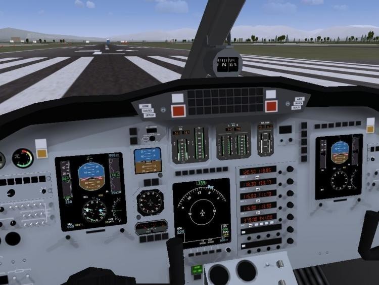
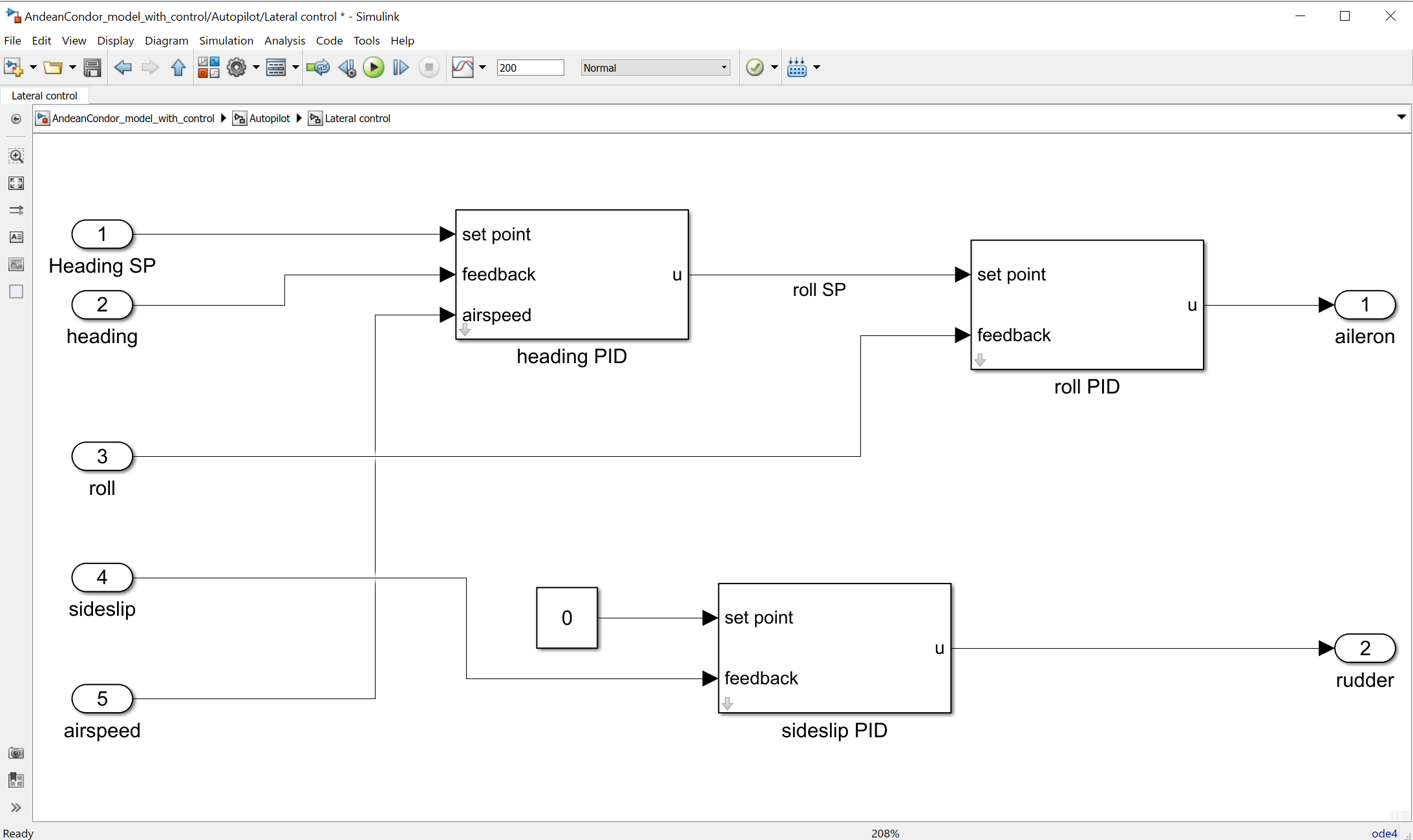
Two windows next to eachother are recommended in order to be able to watch both Simulink and FlightGear at the same time, as shown in the picture below.

You can change the aircraft's starting state by changing the initial conditions vector of the Integrator block. Each of these monitors are configured and located to certain positions for.Run runfg_send_and_receive.bat included in /src, which contains the information needed for the connection between the model and FlightGear and starts a FligthGear version connected with the Simulink model.Open matlab and run Model.slx in order to open the Simulink model.FlightGear version v2017.3 is also required in order to watch the flight in real-time. The Aerospace Blockset Simulink library is needed, which includes many of the built-in blocks used in the model, such as the Flight Instruments blocks. In each loop, the simulator takes throttle and control surfaces’ deflections as inputs, calculates the aircraft's state, and finally outputs the results to Flightgear, an open source flight simulator software, for real-time visualization of the aircraft’s mission. Moreover, the model is able to take into account the effect of wind, in case of hazardous weather conditions. The simulator also calculates forces and moments produced by the engine and the landing gear. The aerodynamic forces and moments acting on the aircraft are determined using polynomial modeling, where each force and moment coefficient is expressed as a polynomial function, extracted from CFD simulations. The simulator operates by solving the airplane’s equations of motion. Various visual options are available including TV/Monitors. The model’s purpose is to get a better understanding on the aircraft’s behavior during the different phases of its mission. Integration with Matlab, Simulink and FlightGear for use with existing University software. ELECTRONIC MEASUREMENT TECHNOLOGY, 2009, 32(2): 28-30.A dynamic flight simulation model for a Blended Wing Body (BWB) Unmanned Aerial Vehicle (UAV), including take-off, cruise, payload drop and landing, using Matlab and Simulink software.
Simulink monitoring flightgear code#
Code generation of simulink models in the hardware-in-loop simulation. Beijing: National Defense Industry Press, 2010. Real-time Simulation of Flight Control System Based on RTW and VxWorks. issue for unmanned helicopter hovering and trajectory tracking performance. Rapid development of real-time control systems in C++ Based on RTW. Nonlinear small-scale helicopter Simulink model and FlightGear simulation. Real-Time Workshop for Use with Simulink (version6) USA: The Math Works Inc 2004. Airborne IMU simulation based on Simulink and FlightGear. You can associate these displays with specific signals in the model by opening the display block and selecting the signal or block that you want to connect to that block. This library contains different types of displays, such as gauges and lamps. Information on AeroSim block user’s Guide. Simulink Dashboard block library of graphical controls and displays. Feng Liang, Rapid Development of UAV Autopilot Using MATLAB/Simulink, American Institute of Aeronautics and Astronautics, AIAA Modeling and Simulation Technologies Conference and Exhibit 5-8 August, 2002.

Research on Time Delay and Compensation for Hardware-in-loop Simulation System on Dual-computer.


 0 kommentar(er)
